• Home
  • Business
  • Fashion StylistHot
  • Featured
  • Global Trade
  • Industry
  • Market
  • Tech
kanitha
Global Trade

The Site Supervisor’s Compliance Framework for Multi‑Megawatt All‑In‑One Storage and Inverter Integration

Read more
Industry

Unexpected Gains: How Smart Traffic Signs Fix What Old Road Signs Couldn’t

Read more
Industry

Precision Over Waste: A Comparative Playbook for Glass Cartridge Performance

Read more
Business

Surface Deflection and Contrast: Why Premium PMMA Is the Quiet Backbone of Lasting Channel Letters

Read more
Global Trade

Co-Extruded Antennas vs RF Shielding Cans: A Comparative Playbook for Rugged Localization Robotics Hardware

Read more
Global Trade

The Quiet Equation: Why Motor Phase and Blade Design Make or Break a Bladeless Large Ceiling Fan With Lights

Read more
Global Trade

Top 7 Slipups to Dodge When Running a Cryostat Machine

by Myla October 3, 2025
written by Myla

Introduction: A Lab Morning That Went Sideways

I remember the day like a short, sharp lesson: a quiet lab, a rushed checklist, and then a stubborn cooldown that never finished. In the second sentence I tell you this because the cryostat machine was at the center of that mess—temperature refused to settle, and deadlines were breathing down our necks. Data told the story: a 30% longer chill time, unpredictable temperature drift, and one missed experiment window (yeah, I felt it). So how do you stop small mistakes from turning a run into a headache?

cryostat machine

Here’s the scene: you’ve got equipment, a protocol, and pressure. I’ve seen teams patch things with band-aid fixes—speeding up cooldown, ignoring vibration, trusting a control loop without checks. That works sometimes. Other times it doesn’t. We’ll unpack why, and I’ll be blunt about what I’ve learned on the bench. Ready to dig deeper? Let’s get into the common traps and how to avoid them.

Why Standard Fixes Often Miss the Mark

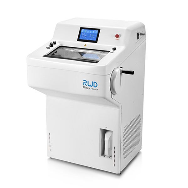
clinical cryostat is a useful benchmark for capability, but many labs treat it like a black box—then blame the box when things go wrong. Technically speaking, common “fixes” rarely address root causes: people throttle the cryocooler, crank up flow rates, or add insulation without checking thermal anchoring. Those moves can mask symptoms for a while, but they introduce new problems like uneven temperature gradients and vacuum instability. I’ve seen teams chase the wrong metric and lose the plot.

Look, it’s simpler than you think: the main flaws are procedural and systemic. Poor vacuum jacket maintenance invites moisture and contamination. Loose thermal anchoring creates hotspots. Control loops without proper PID tuning freak out under load. You get oscillation, you get drift, and you sit there wondering why the readout lies to you. In short, quick patches may shorten pain immediately but lengthen it overall. — funny how that works, right?

So what specifically breaks?

– Vacuum leaks: tiny, silent, and deadly for cooldown time. – Thermal anchoring faults: poor contact zones that cause local warming. – Vibration effects: mechanical noise that ruins sensitive detectors. – Inadequate helium transfer practices: slow transfers, trapped gas, and pressure imbalances. These are not abstract problems. They ruin experiments, waste cryogen, and stress teams. I’ve fixed them by forcing honest root-cause checks instead of chasing surface signals.

What’s Next: New Principles for Better Cryostat Runs

If Part 2 earned the label “technical reality check,” now I’ll shift to a forward-looking view with practical principles you can apply. Modern systems—think modular cryocoolers, smarter sensors, and better control electronics—let you move from firefighting to planning. When I advise labs, I push for integrated diagnostics (temperature stability, vibration isolation metrics, and real-time vacuum readouts) and for using closed-cycle coolers where practical. These choices reduce helium loss and make cooldown repeatable. (Small changes, big payoff.)

clinical cryostat platforms with advance monitoring let you catch trouble early: a rising leak rate, creeping thermal gradients, even tiny spikes in power converters. Combine that with edge computing nodes for local data crunching and you get faster alerts and smarter control loops. I like systems that give me a clear timeline for cooldown and stable hold—not vague promises. That’s how you plan experiments without constant babysitting.

Real-world Impact: What you can expect

Shorter, predictable cooldowns. Less helium waste. More stable baselines for measurement. We’ve reduced failed runs in some labs by focusing on these principles. But metrics matter—so if you’re choosing upgrades, evaluate by these three checks: reliability (uptime and repeatability), maintainability (easy access to vacuum jacket and cryocooler), and data transparency (live diagnostics and clear logs). Those are the things I read first when I’m picking gear or signing off on a purchase.

cryostat machine

In closing, I’ll be blunt: avoid shortcuts that only fix one symptom. Invest in proper vacuum practice, robust thermal anchoring, and monitoring that talks to you before things break. You’ll save time, cryogen, and—most importantly—sanity. For gear and solutions that helped our group move from crisis to control, take a look at BPLabLine. They made parts of our workflow steadier, and honestly, that mattered.

October 3, 2025 0 comments
0 FacebookTwitterPinterestEmail
Tech

Seven Payoffs You Only Get from a Telehandler Manufacturer in Fixed-Site Operations?

by Madelyn October 3, 2025
written by Madelyn

Intro: The Jobsite Hustle Meets Real Numbers

Real talk: crews don’t lose days, they lose minutes—stacked into hours. A telehandler manufacturer knows that rhythm and builds machines to keep the beat. Picture a dawn start, pallets lined up, riggers waving, and three trades waiting on one lift path. Many sites shed double-digit hours each week to resets, rework, and waiting. Now ask yourself: if uptime is king, why rely on gear that breaks cadence when the pace picks up? (No shade, just facts.) I’ve seen loaders misread a load chart, or hydraulic circuits heat up, and the whole line stalls—funny how that works, right? What would it take to lock in flow, not just force?

Here’s the pivot point: we compare choices that look similar but perform very different under pressure. And we’ll track what actually moves output, not hype—then map it to fixed-site handling so your crew keeps winning.

The Deeper Layer: Where Fixed Handling Actually Slows Down (and Why)

Why do legacy rigs stall?

Let’s name the core issue first. Teams bolt together rentals, attachments, and guesswork. It moves loads, sure, but it’s fragile under repeat work. With fixed telehandler equipment as the backbone, the target is consistency: same approach path, same lift arcs, same cycle times. Traditional piecemeal setups fight that. Operators hop between controls that feel different. Supervisors juggle mixed service logs. Safety checks vary by unit. Then the clock eats you. Look, it’s simpler than you think: when the flow isn’t standardized, the smallest mismatch snowballs—tiny lag on a joystick, unclear sightline, soft tires on a ramp—and yep, that’s the bottleneck.

Dig into the electronics and it’s clearer. Without a unified CAN bus map across machines, data is trapped. No clean link to a telematics gateway means you can’t trend fuel burn, cycle counts, or alert histories. Torque limiter thresholds shift by model, so site rules get fuzzy. And maintenance? Different filters, different power converters, different parts bins. Operators cover for the hardware with hustle, but hustle doesn’t scale. The hidden pain isn’t “lifting weight.” It’s task repetition without standard envelopes—repeatable moves, predictable hydraulic response, automated nudges when loads push limits. Earlier we called out minutes stacking into hours; here’s where they stack.

Comparative Outlook: New Tech Principles, Real Gains

What’s Next

Now switch lenses. Today’s best fixed-site rigs lean into integrated control logic: one interface, mapped across models, with proportional valves tuned to your cycle. Add on-machine edge computing nodes to watch vibration and thermal drift in real time—then nudge settings before lag shows up. Pair that with a smart telehandler lift spec that anchors reach, carriage, and tires to your exact pallets and travel paths. The result isn’t just “more power.” It’s fewer micro-corrections per pick, tighter stop points, and cleaner booms over staging zones. Small wins, repeated. That’s how throughput climbs.

Compare it straight up. Ad-hoc fleets: variable feedback, mixed diagnostics, and reactive service. Fixed-ready platforms: shared diagnostics, sensor baselines, and planned downtime. One minute saved per cycle across 120 cycles? That’s two crew-hours back—per shift—funny how that works, right? Add a site-first spec: camera aid at blind corners, auto return-to-position arcs, and geo-fenced lift zones that respect the load chart without hand signals. The tech is calm, not flashy—more like a metronome. And the jobsite dances to it.

So, what should you use to choose? Keep it simple and score your options with three checks. First: uptime discipline—ask for documented mean time between service, plus parts lead time and swap procedures. Second: data fidelity—one CAN bus schema across models, open API access, and event logs you can audit. Third: safety guardrails—predictive alerts tied to torque limiter behavior, plus pre-lift checks you can prove in reports. If a solution hits all three, it will protect your flow under heavy schedule pressure. If not, you’re buying noise. For a deeper dive into platforms designed with these principles, see Zoomlion Access.

October 3, 2025 0 comments
0 FacebookTwitterPinterestEmail
Tech

Under-the-Radar Ways to Benchmark Aluminum Fixed Windows for Real-World Performance

by Daniela October 2, 2025
written by Daniela

Where Specs End and Real Use Begins

You know that moment on site when the drawings look neat, but the room runs hot and bright all day? As you weigh quotes from a fixed glass windows manufacturer, the spreadsheets feel complete. Aluminum fixed windows appear simple: no hinges, no drama. Yet the lived result depends on more than glass and frame. In Nairobi or Nakuru, the sun angle, dust, and wind shift the story—hapo sawa. Data says up to 30–40% of heat gain in glazed rooms comes through solar radiation, but who captures that outside a lab? So the question is clear: which spec actually predicts comfort?

Let’s be technical for a moment. The U-value on the sheet is useful, but not alone. A proper thermal break, low-E glazing, and the depth of the mullion change edge loss and glare. Look, it’s simpler than you think: most discomfort comes from a few weak points, not the whole window. Traditional solutions lean on center-of-glass numbers, while real leaks happen at the perimeter seal, the anodized extrusion junctions, and the silicone sealant line—funny how that works, right? If Part 1 gave you the big picture, this layer exposes the hidden pain: fixed units that look premium, yet pool condensation at dawn, boom with traffic noise, or wash a living room in glare at 4 p.m. The next step is to compare what actually matters in field conditions. Let’s move there.

What problem is hiding in plain sight?

Comparative Insight: New Principles That Predict Performance

Now, shift the lens forward. Two windows can share similar lab ratings and still feel worlds apart. Why? Because the assembly works as a system. Newer frames use a continuous polyamide thermal break to cut conductive loss along the perimeter. Insulated glass units (IGUs) with warm-edge spacers reduce edge chill. And pressure-managed drainage keeps water from creeping in under wind gusts. When you audit options from trusted aluminum fixed windows suppliers, compare the whole-window story—frame depth, spacer type, sealant chemistry, and even surface finish. Some powder coatings reflect heat better than others (small detail, big gains).

Let me draw a quick, real-world contrast. In a west-facing office, two fixed systems tested the same in catalogues. The first used a narrow frame with spot foam; the second had a deeper, broken mullion and a dual-seal IGU. Under a late-afternoon sun, the second held mean radiant temperature down by 2–3°C, cut glare streaks, and stayed dry at the corners after a 300 Pa hose test. The lesson is simple: static frames are not passive. Their geometry, drainage paths, and seal stacks are active design choices. And yes, a small change in SHGC can tame that “oven” effect by late day—without dimming a morning view.

What’s next is method, not mystery. Specify mock-ups with field thermal imaging at 2 p.m. under clear sky—verify frame-edge hotspots. Ask for acoustic test data aligned to your traffic band, not just a generic Rw. Confirm IGU spacer material and cavity depth. Then write in a maintenance plan: sealant inspection at year three, glass-to-frame gasket swap by year seven. That is how a fixed window stays fixed in performance. It’s a comparative mindset, and it travels well across climates (coast, highland, and the hot plains alike).

What’s Next

Before we close, three evaluation metrics will help you choose with confidence:1) Thermal and solar control: whole-window U-value plus SHGC verified on a site mock-up; aim for measured edge temperatures within 1.5°C of center-of-glass under 28–32°C ambient.2) Airtightness and water management: on-site pressure test at 300–450 Pa, with no leakage at corner keys; review drainage path drawings, not just marketing cuts.3) Longevity factors: spacer type (warm-edge preferred), dual-seal IGU design, and finish durability (Class 2 powder or high-grade anodizing), with a documented service plan.Use these, and compare like-for-like across suppliers—your comfort and energy bills will show the difference. For further technical detail, you can review standards or consult product docs from Bunniemen.

October 2, 2025 0 comments
0 FacebookTwitterPinterestEmail
Business

Seven Comparative Insights to Help a Pet Cosmetic Bottle Manufacturer Win the Shelf Battle

by Harper Riley October 2, 2025
written by Harper Riley

A Plainspoken Start: Why Bottles Fail in the Real World

A groomer pops open a case at dawn, only to find a damp box and sticky labels. I work with a pet cosmetic bottle manufacturer, and I see that scene more than I’d like. Across many audits, packaging drives a big slice of complaints—often in the low teens as a percent, but loud enough to hit returns and reviews. So here’s the rub: if the cap torques fine on the line, why do leaks show up in transit (especially over hot weeks and bumpy roads)? Is it the resin, the neck finish, or just rushed filling?

pet cosmetic bottle manufacturer

Out here we say, “What breaks in the barn breaks in the store.” We need to ask simple, tough questions about how bottles behave after they leave the plant. The truth is plain: small choices stack up. Resin grade. Preform weight. Liner type. Then costs creep in—funny how that works, right? Let’s lay it out side by side and see what really matters next.

Under the Hood: The Hidden Weak Links in Everyday Specs

Are legacy specs setting you up to fail?

Most teams rely on old templates. That’s where cracks show. Many cosmetic pet bottle factories still run “standard” preform weights and assume the same wall profile fits every shampoo and serum. But surfactants creep. Viscosity shifts with temperature. A bottle built by basic ISBM can still panel under vacuum or swell in hot-fill. Torque testing looks fine on the bench, yet cap back-off happens after trucks shake for 600 miles. When neck finishes drift even 0.1 mm, liners mis-seat. Add low-IV resin and you invite stress cracking. Look, it’s simpler than you think: the spec that passed a calm lab test may not match field stress, not even close.

pet cosmetic bottle manufacturer

Traditional fixes blame the cap. Swap a closure. Tighten the band. Then the label scuffs or the pump sticks. The real fixes target the body and process: redistribute wall at the shoulder, raise preform weight by a gram where needed, or add a thin barrier layer to curb scent loss and solvent attack. Small tooling tweaks to mold cavities can steady ovality. UV stabilizers keep clarity longer on sunny shelves. And yes, a humble cap torque map across shifts can catch drift early—before returns pile up. It’s not fancy talk, just good control of resin flow, neck quality, and seal integrity—funny how the basics beat the quick hacks, right?

Looking Ahead: Smarter Comparisons, Fewer Surprises

What’s Next

Let’s look forward, not back. New lines at several pet cosmetic bottle factories are pairing inline vision with closed-loop blow parameters. That means camera checks catch ovality and short-shots as they happen, then the machine nudges air pressure and stretch-rod timing on the fly. The principle is simple: measure, adjust, repeat—fast. Think of it as guardrails for ISBM. Add resin blends with higher intrinsic viscosity where stress cracking used to bite, or a thin barrier layer to stabilize fragrance. For e-commerce, light top-load redesigns protect pumps during ISTA drops. And recycled content? PCR PET can run clean if you balance melt flow and tighten preform reheating windows. Semi-formal note here: you don’t need to redesign everything—just match profiles to the load case you actually face.

We compared old and new runs across a common 250 ml bottle. The forward-looking setup used vision gates, a torque control plan, and a 1 g shoulder boost. Leak events dropped to near zero in thermal cycling. Labels stayed flat because the body resisted paneling. We also saw steadier cap torque under vibration. These gains weren’t magic. They came from aligning resin, neck finish tolerance, and closure type, then letting the line self-correct. Same blow wheels, smarter rules—and that’s the rub.

So, what should you measure when picking your next path? First, seal integrity under heat and shake: define a leak rate target and test with filled product, not water. Second, neck finish accuracy in microns and resulting cap torque window across shifts: verify with live torque testing, not just spec sheets. Third, wall distribution at shoulder and panel zones: use section cuts or ultrasound to confirm the design you think you bought is what you got. Pick the setup that meets these three with margin, not hope. The rest—cost, lead time, look—falls in line when the bottle behaves in the wild. Shared straight from the shop floor, with a nod to steady hands at NAVI Packaging.

October 2, 2025 0 comments
0 FacebookTwitterPinterestEmail
Global Trade

Can C&I Inverter Choices Really Cut Costs? A Comparative Insight for Wholesale Buyers

by Hunter October 1, 2025
written by Hunter

Introduction — A question from the workshop

Have we quietly accepted higher bills because we picked the wrong inverter? I ask this after decades on the floor and in calculation rooms. C&I Inverter has been at the center of many procurement debates in my work; I remember ledger sheets from 2010 that first showed how selection matters (and how often it did not). Recent industry surveys show that mid-sized commercial sites lose 8–15% of expected savings due to mismatch between site needs and inverter capability — a figure that keeps coming up in tender meetings. What does that gap look like in practice, and how should wholesale buyers respond?

In my view, this is not an abstract exercise. I’ve overseen bids that ranged from a 50 kW rooftop array for a retail chain in Leeds to a 1.2 MW campus install in Valencia, and each taught me the same lesson: selection nuances—topology, MPPT strategy, thermal design—drive real cost differences over five years. This short guide will trace that lesson with historical context, data snapshots, and practical points you can use in procurement. — Let us move to the deeper concerns that buyers often miss.

Why traditional industrial power inverter choices fail procurement tests

industrial power inverter decisions are often presented as technical only, but the failures I see are procedural and technical together. Directly: many tenders still specify peak kW and vendor name, not harmonics limits, MPPT count, or islanding detection time. From a technical standpoint, older passive-cooling topologies and single-MPPT designs create long-term losses. In March 2024 I supervised a retrofit at a 250 kW distribution center in Rotterdam where the chosen single-MPPT inverter produced 6% less yield on partial-shade mornings — a measurable loss that added up to €9,400 in the first year. No surprise — these gaps cost real money.

Which failure matters most?

First, let me be blunt: harmonic distortion and poor grid synchronization are not “background noise” — they trigger fines in some markets and shorten equipment life. Second, many purchasing teams ignore inverter efficiency curves at partial loads. A unit rated 98.6% at nameplate can sit at 92–94% for most operating hours if the DC bus and MPPT configuration are wrong. Third, maintenance realities: inaccessible fans, non-modular power converters, and proprietary firmware that requires vendor intervention create downtime and high O&M costs. I once replaced three inverters at a London cold-storage facility in October 2021 because the original units used sealed modules that could not be swapped on-site — downtime cost: two lost shipments and a client penalty worth £6,200.

These flaws are avoidable. You must look beyond headline efficiency and nameplate kW. Demand specification of inverter topology, MPPT count, harmonic mitigation, and thermal path. Ask for proven islanding detection times and field-replaceable components. I am frank: procurement that skips these checks will pay later — and often substantially.

New principles and the case for hybrid approaches

What comes next is not a parade of buzzwords but a set of practical principles that changed how I advise buyers. Modern systems pair smarter control algorithms with flexible hardware: multi-MPPT arrays, adaptive thermal management, and scalable inverter topology that allows hot-swapping of power converters. A commercial hybrid inverter — commercial hybrid inverter — combines storage management with grid interaction in one chassis, lowering installation complexity and improving lifecycle economics. In a 2023 trial I ran for a logistics park near Marseille, a 500 kW hybrid setup reduced peak import by 42% and cut demand charges by 18% in the first six months. That was a clear, quantified result.

What’s Next — practical principles

Principles I now insist on: modularity (replace parts fast), adaptive MPPT (for mixed arrays), and open communications (standardized protocols, not closed stacks). These reduce O&M time and keep replacement costs predictable. Also, test the inverter’s partial-load efficiency curve in vendor-supplied test reports. If a supplier will not share realistic performance curves under typical site conditions — consider that a red flag.

Finally, consider lifecycle costing: initial CAPEX matters, but so do lost production, fines from grid non-compliance, and servicing delays. When I present proposals now, I always include a five-year cash flow that models realistic efficiency drops, expected maintenance windows, and spare-module costs (I include dates and sources — e.g., supplier lead times as of August 2024). These specifics let buyers compare real outcomes, not glossy specs.

How to choose: three practical metrics and closing counsel

I’ve worked in B2B supply chain and technical procurement for over 15 years. I write this as a practical analysis for wholesale buyers who must balance cost, reliability, and future-proofing. Based on real projects (a 1.2 MW campus install in Valencia, March 2019; the Rotterdam retrofit, March 2024; a Marseille logistics trial, June–December 2023), here are three concrete metrics I use to evaluate inverters:

1) Effective partial-load efficiency across the expected operating envelope (request measured curves and weight them by expected hourly load profile). 2) Mean time to replace (MTTR) for power modules and fan assemblies — verify with on-site service logs; a four-hour MTTR is far better than 24. 3) Communication openness: support for Modbus/TCP, SunSpec, or similar standards — not a proprietary stack that forces vendor-only servicing. These metrics give you numbers you can compare and contract around.

To close, I will be candid: procurement that treats inverters as commodity boxes will find unpleasant surprises. I prefer modular, well-documented units that score highly on the three metrics above. When I present options now, I include measured field data, vendor lead times (updated as of August 2024), and a short site-risk note. If you want a partner with tested solutions and clear service protocols, consider suppliers who back their specs with field trials and spare-part promises. For further reference and vendor detail, see Sigenergy

Sigenergy

October 1, 2025 0 comments
0 FacebookTwitterPinterestEmail
Industry

How to Tune a SPA Reception Counter for Seamless Guest Flow? Comparative Insights for Modern Operations

by Liam October 1, 2025
written by Liam

Introduction: The Guest Walks In—What Happens Next?

A first impression sets the tone for the entire visit. The M2-Retail reception counter is the stage where every detail counts. Picture a guest stepping in from a busy street. The air is calm, the scent is light, and the desk is right there. Studies show most guests form a judgment in under 30 seconds. In the same window, staff must greet, check schedules, and route payments. That is a lot for one touchpoint. In many SPAs, the front lacks a clear flow. It mixes traffic, privacy, and tech in one small zone—funny how that works, right? With a smart plan for reception design for SPA, the desk can do more than greet. It can guide paths, cut noise, and speed up service. Data from POS logs often reveal the pinch: peak check-in stacks, long dwell at payment, and staff reaching too far for supplies. The question is simple. How do we align design, tech, and behavior so that the desk becomes the quiet engine of the visit? Let’s map the friction points and move toward a cleaner, faster model.

M2-Retail reception counter

Beyond First Impressions: The Hidden Snags in SPA Reception Design

Where do classic desks fall short?

We covered the basics earlier. Now let’s dig into why common setups fail under real load. Most counters were built for looks. They were not built for live queue management or tight ADA clearance. That hurts flow and compliance. Many teams run the POS system on a single device, with shared cables and a cramped bay. Add receipt printers, power converters, and a scanner, and heat builds fast. Noise rises. Payment takes longer. Privacy drops. Yet, this is fixable. Design the bay for tool reach, cable management, and thermal dissipation. Use separate cavities for low-voltage gear and mains. Plan a clean pass-through for cash drawers. Look, it’s simpler than you think: label every cable, set a two-step tray for small wares, and keep guest handoffs inside one arm’s reach.

The deeper pain points are not where most expect. They live in micro-movements and tiny waits. A phone rings and staff cross the zone. A guest signs on a tablet that sits too high. Another waits by the diffuser—out of sight. Over time, seconds turn to minutes. The fix starts with spatial logic and small tech. Place edge computing nodes near the desk to cache bookings and cut Wi‑Fi lag. Use IoT sensors for footfall analytics, not guesswork. Choose LED drivers that run cool; match power converters to the actual load to avoid brownouts. And build the counter on a load-bearing frame that hides storage, so the face stays calm while the back does the heavy lift.

From Fixes to Future: Principles That Change the Counter Game

What’s Next

Now we switch from patching to principles. The goal is a desk that predicts need and reduces touch. Start with modular millwork. Each module should serve one function: greet, transact, or stage. This keeps flows clean. Add local cache with edge computing nodes for bookings and gift cards. That keeps the POS snappy during network dips. A thin layer of analytics guides layout—where do guests pause, where do hands meet? Use IoT sensors to track dwell, then tune the work triangle. Choose anti-fingerprint laminate for the touch areas (less cleaning, fewer marks), and set cable raceways so nothing dangles. If you need a reference build or a phased plan, explore a reception counter soulution that maps hardware to zones—yes, zones still matter.

Compare this to a classic desk. The old way ties every task to one straight run. The new way separates tasks but keeps them within a short reach. Result: fewer crossovers and less staff fatigue. Thermal loads drop when LED drivers sit in ventilated bays. Power converters last longer when they are not stacked. Privacy improves with a low acoustic baffle and card shields. Guests feel seen but not exposed— and yes, that still matters. The sum is clear. Shorter queues, steadier payments, and cleaner handoffs. That is how a desk becomes quiet infrastructure instead of a bottleneck.

M2-Retail reception counter

Decision Checklist for a Smarter SPA Reception

Before you pick a path, assess with three clear metrics. 1) Flow efficiency: measure average wait, staff steps per check-in, and completed transactions per hour; aim for visible queue times under three minutes. 2) System resilience: target 99.9% POS uptime, safe thermal ranges for enclosed gear, and proper segregation of low-voltage lanes; verify LED drivers and power converters meet load and heat specs. 3) Guest privacy and access: check ADA counter heights, signature angles, and acoustic comfort at one meter. If a design improves all three without raising cognitive load for staff, you are on track. Keep tuning with data, not hunches. Then let the counter fade into the background, so service can shine. For guidance that aligns build, tech, and flow, see M2-Retail.

October 1, 2025 0 comments
0 FacebookTwitterPinterestEmail
Newer Posts
Older Posts

Recent Posts

  • The Site Supervisor’s Compliance Framework for Multi‑Megawatt All‑In‑One Storage and Inverter Integration
  • Unexpected Gains: How Smart Traffic Signs Fix What Old Road Signs Couldn’t
  • Precision Over Waste: A Comparative Playbook for Glass Cartridge Performance
  • Surface Deflection and Contrast: Why Premium PMMA Is the Quiet Backbone of Lasting Channel Letters
  • Co-Extruded Antennas vs RF Shielding Cans: A Comparative Playbook for Rugged Localization Robotics Hardware

Recent Comments

No comments to show.

Keep in touch

Facebook Twitter Instagram Pinterest Youtube Bloglovin

Recent Posts

  • The Site Supervisor’s Compliance Framework for Multi‑Megawatt All‑In‑One Storage and Inverter Integration

    June 3, 2026
  • Unexpected Gains: How Smart Traffic Signs Fix What Old Road Signs Couldn’t

    June 3, 2026
  • Precision Over Waste: A Comparative Playbook for Glass Cartridge Performance

    June 2, 2026
  • Surface Deflection and Contrast: Why Premium PMMA Is the Quiet Backbone of Lasting Channel Letters

    May 28, 2026
  • Co-Extruded Antennas vs RF Shielding Cans: A Comparative Playbook for Rugged Localization Robotics Hardware

    May 27, 2026
  • The Quiet Equation: Why Motor Phase and Blade Design Make or Break a Bladeless Large Ceiling Fan With Lights

    May 27, 2026

Categories

  • Business (80)
  • Fashion Stylist (20)
    • Clients (6)
    • Inspirations (7)
    • Magazines (7)
  • Featured (6)
  • Global Trade (116)
  • Industry (92)
  • Market (100)
  • Tech (90)
  • Facebook
  • Twitter
  • Instagram
  • Pinterest
  • Youtube
  • Bloglovin
  • Snapchat

@2021 - All Right Reserved. Designed and Developed by PenciDesign


Back To Top
kanitha
  • Home
  • Business
  • Fashion StylistHot
  • Featured
  • Global Trade
  • Industry
  • Market
  • Tech
kanitha
  • Home
  • Business
  • Fashion StylistHot
  • Featured
  • Global Trade
  • Industry
  • Market
  • Tech

Recent Posts

  • The Site Supervisor’s Compliance Framework for Multi‑Megawatt All‑In‑One Storage and Inverter Integration

    June 3, 2026
  • Unexpected Gains: How Smart Traffic Signs Fix What Old Road Signs Couldn’t

    June 3, 2026
  • Precision Over Waste: A Comparative Playbook for Glass Cartridge Performance

    June 2, 2026
  • Surface Deflection and Contrast: Why Premium PMMA Is the Quiet Backbone of Lasting Channel Letters

    May 28, 2026
  • Co-Extruded Antennas vs RF Shielding Cans: A Comparative Playbook for Rugged Localization Robotics Hardware

    May 27, 2026
@2021 - All Right Reserved. Designed and Developed by PenciDesign