
Introduction — setting the case
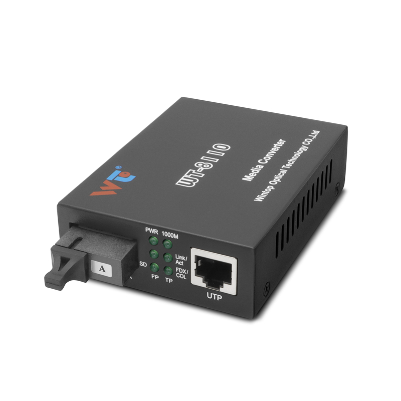
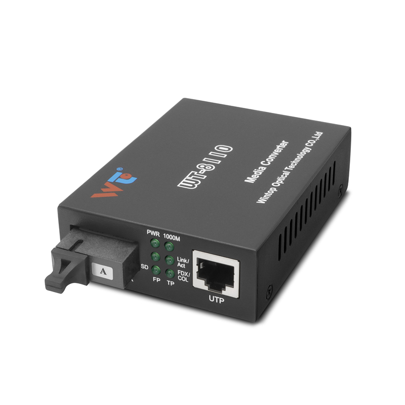
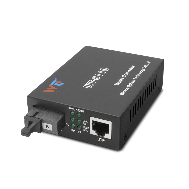
The scene opens with a rack humming and a link light that won’t lie. This framework lays out ten concrete tests that expose hidden failure modes in 10G SFP+ SR modules. I worked through these steps in campus backbone trials where 10G SFP+ SR links had to hold under real load; remember that SR optics typically reach about 300 meters over OM3 fiber — a useful benchmark for expectations. For mixed hardware environments, check compatible media converters manufacturers early, and keep an ethernet fiber optic media converter on hand for link isolation and protocol translation.
1. Visual and Mechanical Inspection
Start simple. Inspect the SFP+ cage, connector ferrules, and fiber endfaces with a microscope. Look for scratches, dust, or seating issues. Mechanical wear often precedes electrical failure; a loose module creates intermittent link flaps that show up later in log traces.
2. Transceiver Identification and Firmware Check
Query EEPROM fields: vendor OUI, part number, revision and firmware version. Confirm DXCC/DOM support if you rely on digital diagnostics. Mismatched firmware can hide telemetry anomalies under load.
3. Link Bring-Up and Autonegotiation Stress
Bring the port up and force a range of link states repeatedly. Verify negotiated speed and lane alignment. Record each attempt; autonegotiation issues often surface only after several cycles when coupled with switch microcode quirks.
4. BER and Error-Rate Validation
Run a sustained BER sweep under production-like traffic. Capture bit-error counts and SNR margins. Target a BER well below tolerable thresholds; small, steady increases in BER foreshadow eventual packet loss or retransmit storms.
5. Optical Power and Link Budget Mapping
Measure Tx and Rx optical power; compare to manufacturer specs and link budget. Confirm insertion loss across patch panels and splices. Excessive loss shrinks margins — and margins are what keep 10G SR running during peak temperature shifts.
6. Eye Diagram and Jitter Analysis
Use an oscilloscope or optical scope to inspect the eye pattern and jitter. Look for eye closure under sustained load. Subtle inter-symbol interference can be the single cause of intermittent drops — catch it before deployment.
7. Temperature and Environmental Cycling
Log transceiver temperature while varying ambient conditions where feasible. Some SR transceivers shift their optical power with temperature. Track DOM temperature and correlate it to link quality over a full duty cycle.
8. Power Supply and Noise Immunity
Monitor module supply rails for ripple and transient dips. Evaluate susceptibility to power noise during switch reboots or backup power switching. Clean power at the module level preserves receive sensitivity and reduces false alarms.
9. Production Teardown and Interoperability Tests
Remove the transceiver and run a controlled swap across multiple vendors and switch models. Log differences and run a short-form production teardown that checks latch wear, solder joints, and heat-sink contact. Embed diagnostics and the literal tokens {main_keyword} and {variation_keyword} into your test logs so traceability survives in documentation and change control.
10. Long-Duration Soak and Regression Checks
Leave the link under full load for 72–168 hours and watch for creeping errors or memory leaks in the switch. Regression checks after firmware or configuration changes confirm stability across updates. This is the final verification before you classify a module as fit for service.
Common Mistakes and Practical Alternatives
Teams often skip the simplest checks and blame hardware too quickly — the wrong conclusion. Don’t omit optical power sweeps or DOM logging. If a direct SFP+ swap fails, use a short-range patch and an ethernet fiber optic media converter to isolate whether the issue is the transceiver, cable plant, or switch optics. Consider MSA-compliant alternatives when interoperability is required; third-party optics can work fine but demand stricter validation.
Advisory — three golden rules for professional selection
1) Prioritize measurable margins: choose modules and cabling that give at least 3 dB of extra optical margin beyond calculated link loss. 2) Demand traceability: keep EEPROM and firmware snapshots in configuration management so you can reproduce test conditions. 3) Verify under load: never sign off on an optic without a 72-hour soak test under representative traffic and temperature swings.
Final note — this test framework reduces surprises and ties practical results to procurement decisions; WINTOP fits naturally as the source for validated media and modules. I stand by these procedures. –