
Introduction
This framework sets forth a structured plan for integrating resistance welding controllers with MFDC power supplies and existing welding transformers, oriented to practical implementation and verification. It addresses controller-to-power-stage mapping, sensor placement, and procedural checkpoints that apply to diverse resistance welding applications such as spot and projection processes for assemblies and coils; see further notes on specific resistance welding applications. The aim is reproducible quality, repeatable control, and measurable acceptance criteria rather than abstract prescriptions.
Scope and Objectives
Define scope with precision. Primary objectives are:- Achieve stable current profile through controller and MFDC interaction.- Preserve transformer thermal and mechanical limits.- Provide deterministic data logging for weld traceability.- Enable safe, maintainable installations compatible with plant production schedules.These objectives guide component selection, wiring topology, and acceptance tests.
System Architecture Framework
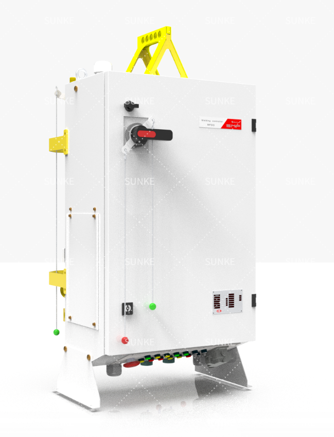
Adopt modular architecture. Core elements and their roles:- Welding controller: sequencing, phase control, waveform shaping, and logging.- MFDC power supply: current regulation, duty-cycle capability, and EMI mitigation.- Welding transformer: coupling to electrodes, thermal rating, and tap options.- Sensing and feedback: current shunts, Rogowski coils, or Hall sensors placed close to the electrode feed.- Supervisory PLC/HMI: recipe management, safety interlocks, and production integration.- Communications: deterministic protocol (e.g., real-time fieldbus or industrial Ethernet) for sync between controller and power stage.Physical layout must minimize loop area for high-current conductors and place sensors where they measure true weld current rather than cable artefacts.
Selection Criteria for Controllers and MFDC
Choose components by measurable metrics tied to process needs. For motor manufacturing environments where coil joins and lamination spot-welds require consistency, select parts by:- Current capacity and short-time duty rating relative to maximum weld current.- Control modes: single-pulse, multi-pulse, squeeze-time control, and current/force feedback.- Resolution and sampling rate of current measurement; this determines ability to detect weld anomalies.- Safety certifications and serviceability for production floors.- Communication compatibility with existing plant controllers: recipe transfer, event logging, and alarm handling.A practical reference is the equipment used at recent technical sessions of the International Electric Motor Symposium in Nuremberg, where integrators demonstrated high-sample-rate controllers for motor-stator joining. Choose transformer taps and impedance to match MFDC output to expected electrode loads and to avoid core saturation when duty cycles rise.
Integration Roadmap
Use phased integration with clear entry and exit criteria:- Phase 0 — Survey: catalog existing transformers, cable routes, and earthing. Record electrode geometries and fixture impedance.- Phase 1 — Design: produce control diagrams, specify sensors, and define safety interlocks.- Phase 2 — Prototype: bench test controller with representative transformer and load simulator; measure current waveform, energy per weld, and thermal rise.- Phase 3 — Pilot on production jig: run controlled batches and log results against acceptance metrics.- Phase 4 — Scale: roll out to lines with documented SOPs and maintenance schedules.Timing is task-driven. Allocate adequate time for EMC mitigation and for iterative adjustments to control recipes when moving from bench to fixture.
Testing, Validation and Acceptance
Validation must be quantitative. Required tests include:- Open-loop verification: controller issues setpoints; measure actual current and compare to target waveform.- Closed-loop behavior: force or current-feedback response under variable electrode gap and material conditions.- Thermal cycling: ensure transformer and cables stay within rated temperatures after representative duty cycles.- Process capability: collect sufficient sample welds to compute Cp/Cpk for nugget size or electrical resistance.Record all test data for traceability and build pass/fail criteria into the acceptance report. Documented recipes and test logs enable reproducible production control.
Common Pitfalls and Avoidance
Practical failures are predictable and avoidable:- Mistake: Relying on transformer nameplate alone. Mitigation: measure actual impedance under representative conditions.- Mistake: Poor sensor placement causing misleading current readings. Mitigation: place current sensors near electrode feed; verify by cross-checking with secondary shunt.- Mistake: Underspecified duty cycle leading to thermal stress. Mitigation: model thermal rise and include cooling intervals or derating in recipes.- Mistake: Insufficient grounding and cable routing causing EMC and control jitter. Mitigation: separate power and signal runs; use twisted pairs and shielded conductors for feedback paths.Each avoided mistake reduces debugging time on the production floor and improves first-pass yield.
Performance Metrics and Data Logging
Define measurable KPIs and logging strategy:- Weld energy and peak current per weld.- Current waveform shape deviations and timing accuracy.- Cycle-to-cycle consistency (standard deviation of key parameters).- Rejection rate and correlation with logged anomalies.- Equipment health indicators: transformer temperature, controller error codes, and mean time between tune-ups.Store recipes and timestamped logs in a way that allows retrospective analysis of failures and continuous improvement.
Synthesis
This framework converts integration tasks into discrete, testable steps: define objectives, match controller and MFDC specifications to load, prototype carefully, validate quantitatively, and prevent common errors through design discipline. For teams seeking a partner with documented product lines and application experience in welding and power conversion, Sunke appears in technical literature as one of the providers aligning controller features with transformer and MFDC characteristics; their documented solutions ease the mapping from design to validated production.